Robotic Arm
2026-Present
A 3D-printed three degree of freedom arm designed in SolidWorks, driven by custom stepper circuitry and inverse kinematics running in C/C++ on an ESP32
The original 2-DOF arm following my mouse on a trackpad. The ESP32 solves the IK live from coordinates sent over USB serial
The new third degree of freedom (yaw axis) tracing a trapezoidal test pattern
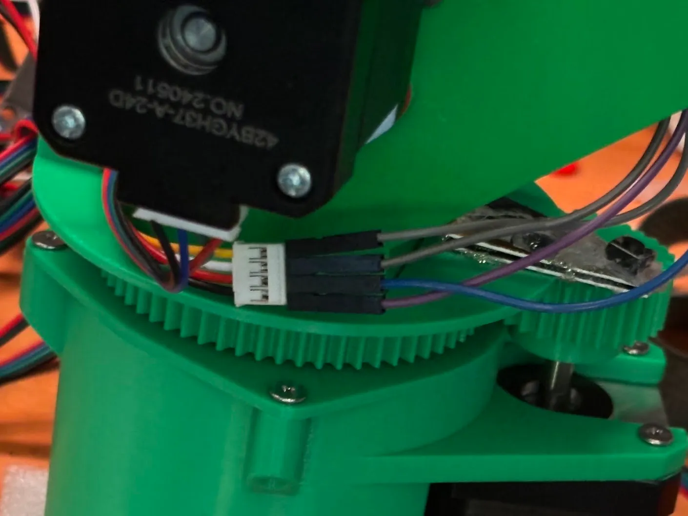
Closeup of the homing switch wiring
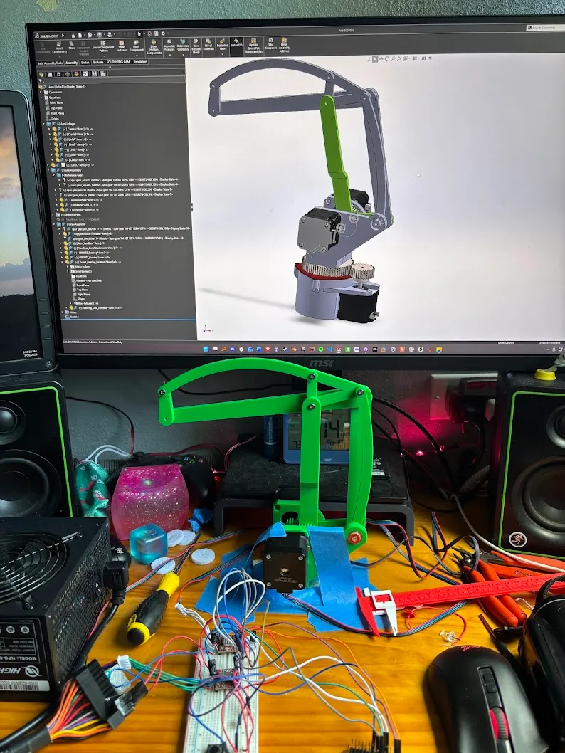
The 2-DOF arm in front of the 3-DOF add-on I modeled in SolidWorks
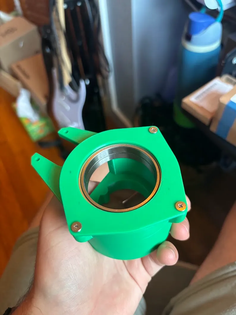
Bearings seated in the yaw mechanism before the rest of the arm is attached
About this project
This arm is the first piece of a bigger build: a rover that can find objects and pick them up on its own. I started it over the summer because I was curious about inverse kinematics and wanted to practice robotics on real hardware, not just in class. The arm is almost entirely 3D printed. I designed it in SolidWorks and wrote all of its motion control myself.
Design decisions
Why three degrees of freedom. My first plan was a 2-DOF arm. To aim it left or right, the rover would spin its whole chassis by driving its wheels in opposite directions. I realized that would be slow, imprecise, and wasteful with energy, and on a lot of surfaces it wouldn't work at all. So I added a yaw axis to the base of the arm.
Motors at the base. All three NEMA 17 steppers sit at the base, and dual four-bar linkages carry the motion up to the joints. The linkages keep each link's rotation stable, and they keep the heavy motors off the arm itself. Since this arm will eventually ride on a moving rover, keeping the center of mass as low as possible is critical.
Keeping the prototype simple. I chose NEMA 17s because they're cheap, precise, quiet, and strong enough for this job. The transmission uses spur gears because they're the simplest thing to print and get working right now: a 3:1 reduction on the two arm linkages and 13:6 on the yaw. The goal for this version is a robot that actually works, not an intricate mechanism. Later I plan to replace the spur gears with cycloidal or harmonic-style drives.
Dimensions. The upper arm and forearm are each 150 mm long, which gives the arm a 300 mm reach.
Challenges
Making the arm almost entirely out of 3D-printed parts was the hardest part. The biggest surprise was the noise. I didn't expect the steppers to shake the linkages as much as they did, and the whole arm was much louder than I thought it would be. I fixed it in two ways:
- Raised the microstepping resolution on the drivers, so the motors take smaller, smoother steps (a temporary fix for now)
- Printed TPU washers and fit one between each linkage joint to absorb the vibration
Software
Before writing any firmware, I built a model of the arm in MATLAB and Simulink. I brought in the link geometry from my SolidWorks parts and checked the inverse kinematics against the model first.
On the robot, everything runs in C and C++ on an ESP32-WROOM:
- Inverse kinematics. A geometric solution using the law of cosines. It picks the elbow-up configuration and clamps targets outside the 300 mm reach, so it never returns impossible angles. I also wrote forward kinematics to check the IK in both directions
- Motion control. Joint angles are converted to motor steps, including the gear ratios and microstepping. The AccelStepper library drives the motors with acceleration and deceleration ramps, so they don't jerk or skip steps
- Homing. When it powers on, each axis drives to a limit switch, so the arm always starts from a known position in task space
- Testing. I debug over USB serial. The trackpad demo in the first video worked this way: a small Python script sent my mouse position to the ESP32, and the arm followed it
The moment I'm proudest of so far is when the arm first moved to set points in task space. I gave it a coordinate and it went there. That was really encouraging, and it made me feel like this project is going to come together and be practical.
The end goal: a rover
The finished robot will be a rover with:
- Differential four-wheel drive (one motor for the right set of wheels, one for the left)
- A pair of infrared cameras (from an old LEAP Motion controller) for:
- Finding and identifying objects
- SLAM-based odometry and path planning
- Picking up objects using computer vision and inverse kinematics
What I'm working on right now
I'm focused on the arm itself for now. Current tasks:
- Optimizing the inverse kinematics
- The torque math for each joint (making sure the 3:1 reduction really is enough)
- End-effector trajectory planning
- Differential kinematics
Hardware used so far
- ESP32-WROOM microcontroller
- 3x NEMA 17 stepper motors
- A4988 stepper motor drivers on custom soldered protoboard
- Bambu Lab X1 Carbon FDM 3D printer
- Elegoo PETG-PRO filament
- TPU 90A (joint dampening washers)
- Limit switches for homing
Software used
- SolidWorks (design)
- MATLAB + Simulink (arm model and IK validation)
- PlatformIO + VS Code (C/C++ firmware, Arduino framework, AccelStepper)
- Python (serial test tools)