Romi w/ Dual 4-Bar Actuated Arm
2026
RBE 2001 final project: a Romi rover with a 3D-printed dual four-bar arm that places blocks on shelves at different heights, driven by inverse kinematics on an ATmega32U4
Final demonstration of our robot
Testing grabbing behavior
About this project
This was our team's final project for RBE 2001 (Unified Robotics I) at WPI, built with Alfredo J. and Nate R. on a Pololu Romi chassis. The robot had to:
- Move two blocks to two different positions on a shelf without touching the shelf itself
- Tuck its arm away afterwards
- Drive to an exact final position, using a mix of forward and inverse kinematics for both the arm and the drivetrain
I designed the arm mechanism and programmed its motion. I also helped with the drivetrain odometry, the inverse kinematics, and the servo firmware.
Designing the arm
The arm uses two independent four-bar linkages, and the claw uses a smaller four-bar for each finger. I chose this from the start. The claw has to go into the shelves straight every time, so it needs to stay horizontal. A four-bar keeps it level on its own. We didn't need an extra degree of freedom at the claw, and a wrist joint would have added complexity we didn't need. The dual four-bar also makes the arm stiffer and simplifies the whole mechanism.
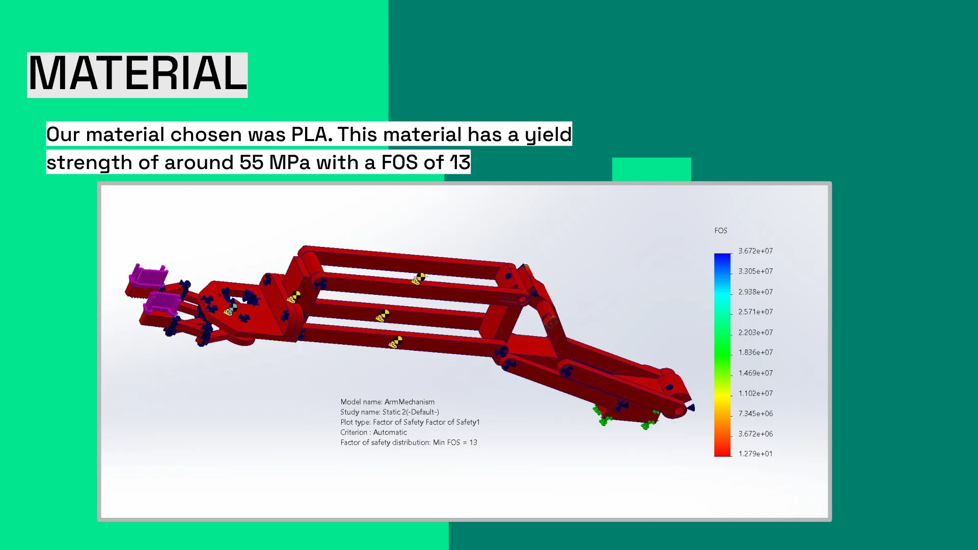
Every custom part is 3D printed in PLA. I used SolidWorks to check that the design would hold up:
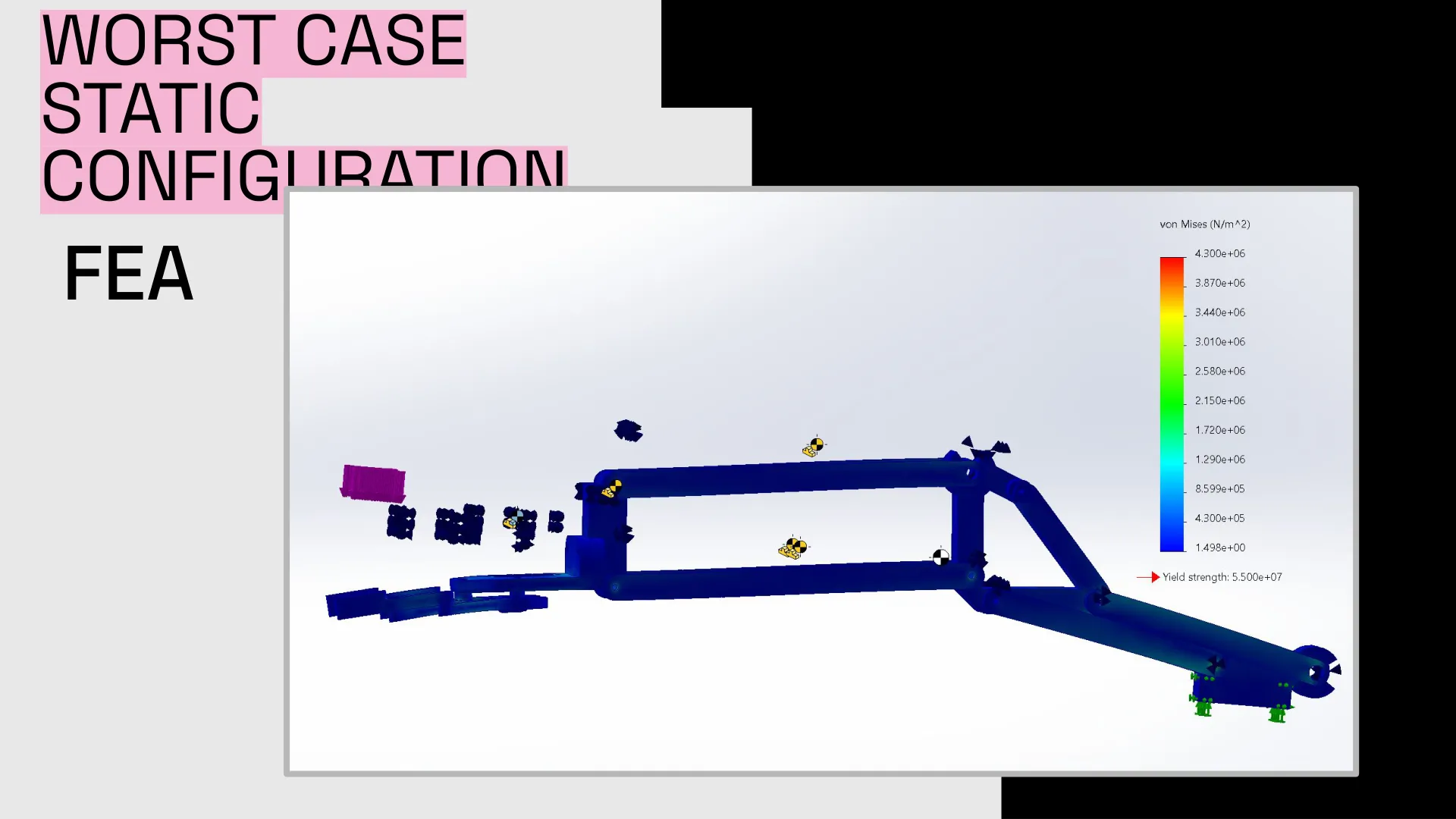
- FEA on the worst-case static pose gave a minimum factor of safety of about 13
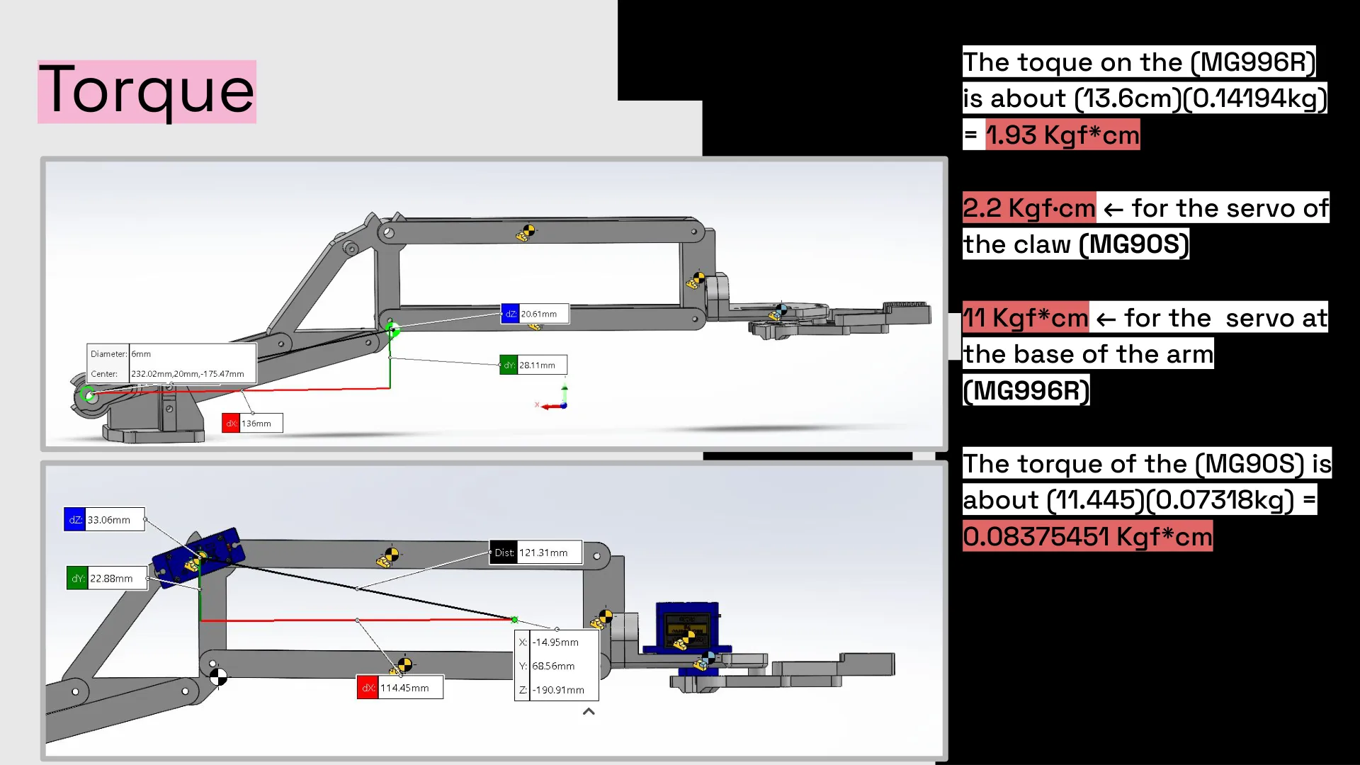
- Torque math for each servo: an MG996R at the base of the arm and MG90S servos for the other joints and the claw
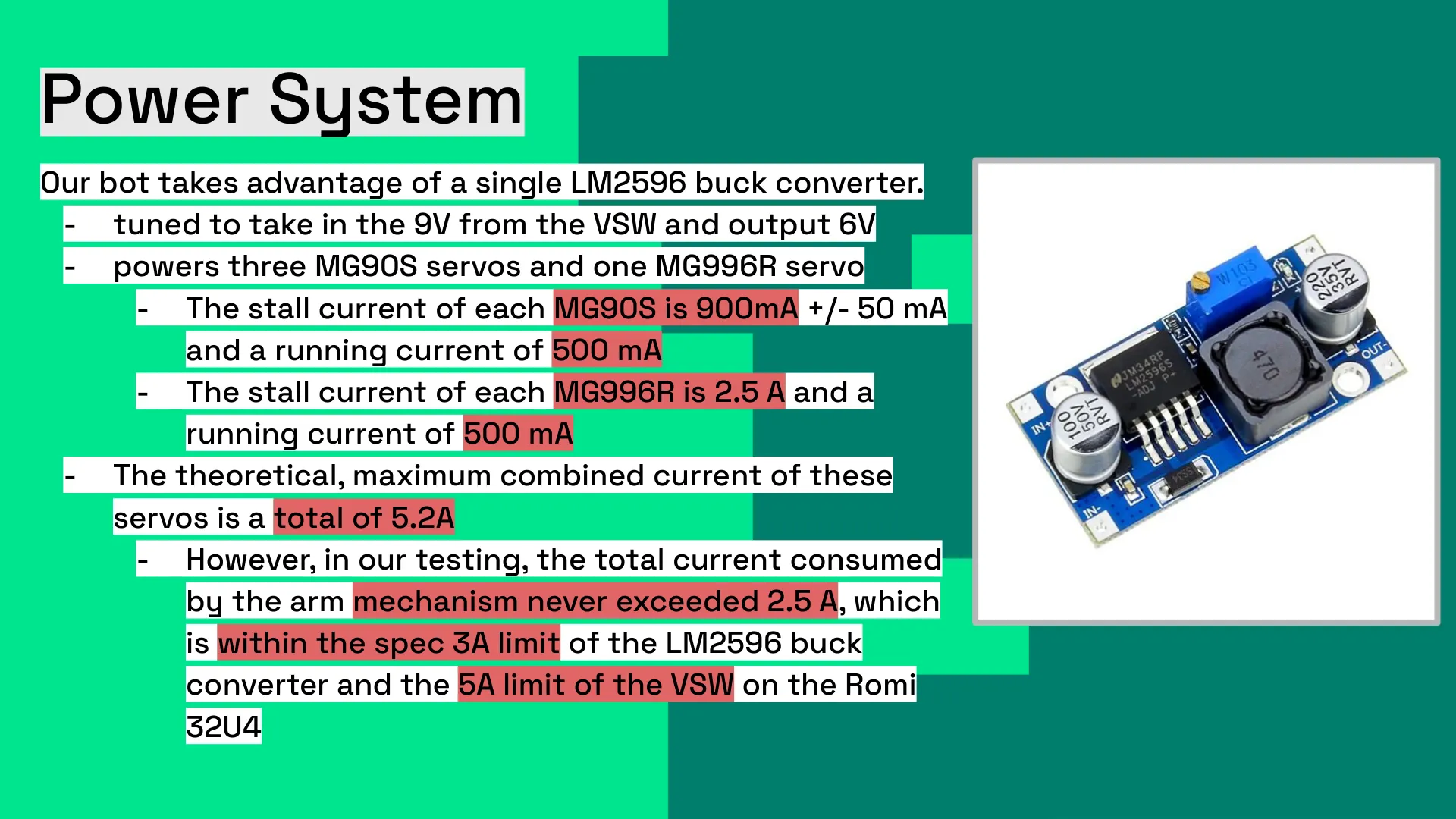
- A power budget. One LM2596 buck converter steps the Romi's 9 V supply down to 6 V for the servos. In testing, the arm never drew more than 2.5 A, which is within the converter's 3 A limit
Programming the arm
The firmware is C++ on the Romi's ATmega32U4:
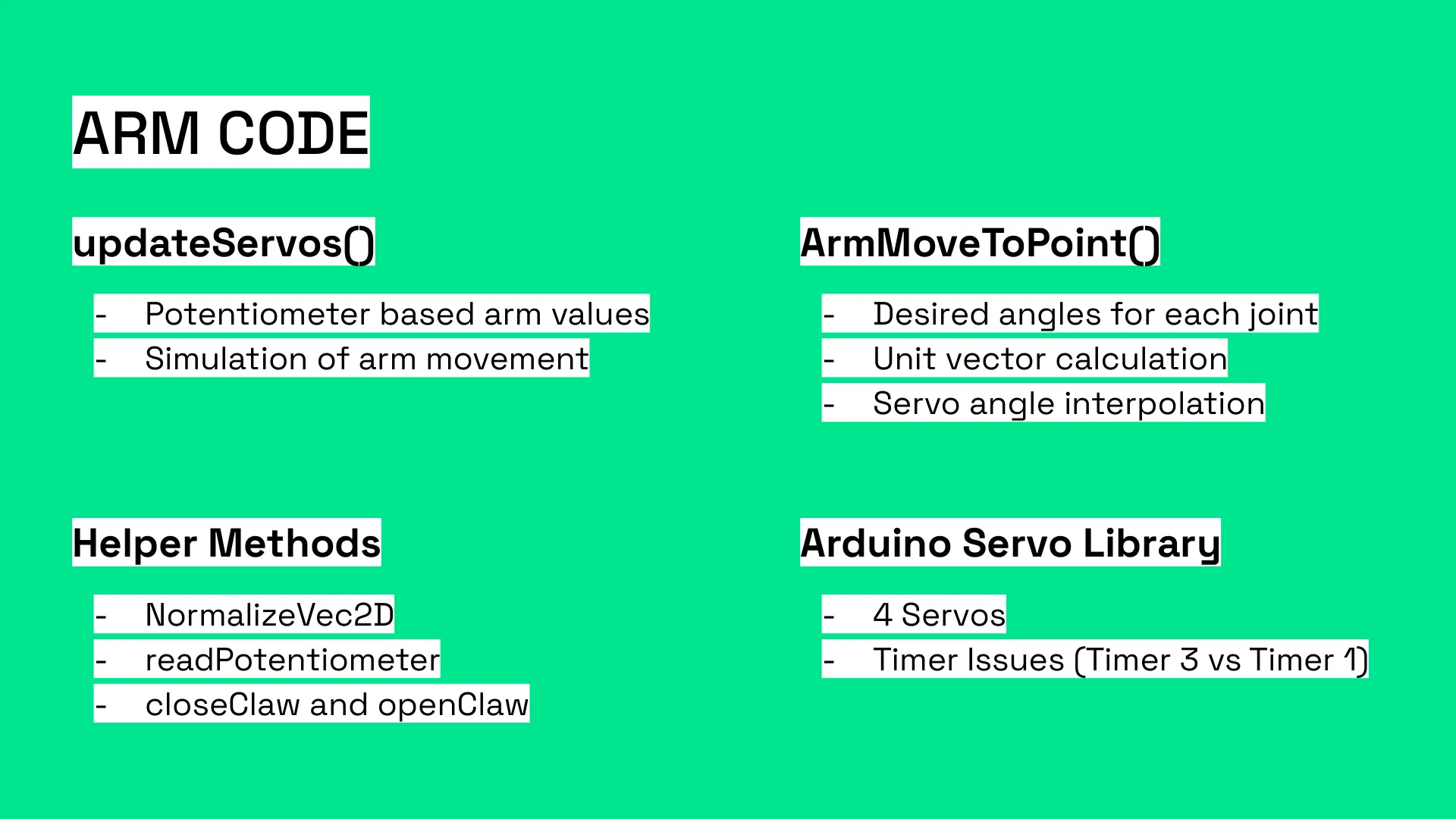
- Inverse kinematics. A geometric law-of-cosines solution for the 90 mm lower arm and 140 mm forearm, with angle offsets that account for the linkage geometry
- Task-space waypoints. To avoid touching the shelf, the arm doesn't move straight to a block. It follows a series of waypoints that I planned out and hard-coded into the final version: into the shelf, release the block, back out, up to the next level, and so on
- Drivetrain. Wheel-encoder odometry tracks the robot's position, and a proportional drive-to-point controller steers it to its destination
- Tuning tools. Two potentiometers could drive the arm directly in task space, and live plots in Teleplot showed the joint angles while we tuned
The timer problem. The course's servo library produces its PWM signals from the ATmega32U4's hardware timers (Timer 3 and Timer 4), and that only works on a few pins. Timer 4 is also shared with the drive motors' speed controller. The arm needed four servos: a mirrored pair on one joint, a third arm joint, and the claw. That was more than the library could run. So we switched to the standard Arduino Servo library, which generates the pulses from Timer 1 interrupts and can drive servos on almost any pin. After that, all four servos ran without interfering with the drivetrain.
Final presentation